
· AstroBAT Team · 5 min read
Anatomy of a BMS: What's Inside a Satellite Battery Pack
When people picture a satellite in orbit, they usually imagine solar panels, an antenna, or an optical payload. Far less visible — but just as critical — is the Battery Management System (BMS): the electronics that keep the battery pack alive through eclipses, radiation, and extreme thermal cycling, in an environment where there is no such thing as a reboot or a service call.
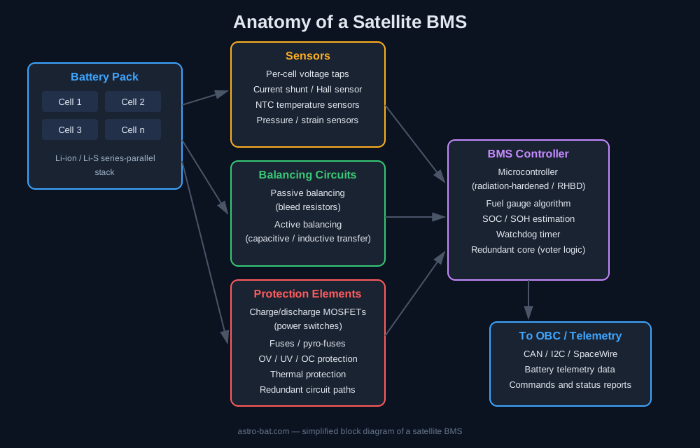
In this article, we’ll break down the architecture of a satellite BMS using a simple block diagram and look at what its three core blocks actually do: sensors, balancing circuits, and protection elements.
Why a satellite BMS is different from a terrestrial one
A battery pack on Earth enjoys a few luxuries we don’t have in orbit:
- If something fails, a technician can swap a cell or replace the BMS board.
- Temperature can be managed with ventilation or active cooling.
- The electronics aren’t bathed in cosmic radiation.
None of that applies once you’re on orbit. A satellite BMS has to be designed with redundancy, radiation hardening (RHBD – Radiation Hardened by Design), and the ability to run autonomously for months or years without any human intervention. That’s why the architecture splits cleanly into distinct functional blocks, each with its own job — and its own redundancy. As the Rad-Hard components are very expensive for LEO orbits there are available commercial components not designed for the radiation environment with flight heritage in aerospace.
The block diagram: a bird’s-eye view
Below is a simplified diagram of a typical satellite BMS. The battery pack feeds into three parallel subsystems — sensors, balancing circuits, and protection elements — all of which report to a central controller. That controller, in turn, sends telemetry and status reports up to the onboard computer (OBC).
Let’s walk through each block in more detail.
1. Sensors — the eyes and ears of the system
A BMS is only as good as the data feeding it. That’s why every pack carries several layers of sensing:
Per-cell voltage monitoring Every cell (or group of parallel cells) has its own voltage-sensing tap. This lets the system catch a weak cell before it drags down the whole stack — one over-voltage or under-voltage cell in a series string can dramatically shorten the life of the entire pack.
Current sensing Usually a shunt resistor or a Hall-effect sensor tracks current flowing into and out of the pack. This measurement is essential for computing State of Charge (SOC) via coulomb counting.
Temperature sensors NTC thermistors distributed across the pack track the thermal gradient. In vacuum, heat can’t be carried away by convection, so even small imbalances in charging can lead to localized overheating — temperature data is one of the most important inputs to the protection logic.
Additional sensors Some packs also include pressure or strain sensors to detect cell swelling, an early warning sign of degradation or an internal fault.
2. Balancing circuits — keeping the stack in sync
Cells in a series string never charge or discharge perfectly evenly — small manufacturing variances, temperature differences, and internal resistance mismatches accumulate over time. Balancing circuits exist to correct for that:
Passive balancing The simplest approach — excess energy from a “fuller” cell is simply burned off as heat through a bleed resistor. It’s cheap and reliable, but wasteful, since the energy is lost rather than used.
Active balancing More sophisticated satellite packs use capacitive or inductive circuits that physically move energy from a “fuller” cell to a “weaker” one. This is far more energy-efficient, but it adds complexity and more components that need to survive radiation and thermal cycling.
The choice between passive and active balancing is typically a trade-off between mass, reliability, and energy efficiency for the mission at hand.
3. Protection elements — the last line of defense
This is the block that decides whether the pack survives an anomaly:
Charge/discharge MOSFETs The controller uses these power switches to fully disconnect the charge or discharge path the moment a sensor reports a dangerous condition.
Fuses and pyro-fuses These act as a final, irreversible layer of protection for catastrophic failures — when software or semiconductor protection fails, a physical fuse breaks the circuit permanently.
OV/UV/OC protection Independent circuits monitor for overvoltage, undervoltage, and overcurrent — often implemented as a separate analog “watchdog” circuit that’s independent of the main microcontroller, so protection still works even if there’s a software fault.
Thermal protection and redundancy Critical protection functions in satellite BMS designs are almost always duplicated or triplicated (dual/triple redundant), because a single point of failure in the protection chain can mean the loss of the entire mission.
The controller: the brain that ties it all together
At the center of the diagram sits the BMS microcontroller — in best case is a radiation-hardened (RHBD) chip that:
- computes State of Charge (SOC) and State of Health (SOH) using fuel gauge algorithms,
- evaluates sensor data and decides when to trigger balancing or protection circuits,
- runs under a watchdog timer that can reset the system if it locks up (for example, after a Single Event Upset caused by cosmic radiation),
- communicates with the onboard computer (OBC) over a bus such as CAN, I2C, or SpaceWire, sending telemetry and receiving commands.
Wrapping up
A satellite BMS isn’t a single chip — it’s the interplay of three tightly coupled subsystems: sensors that measure, balancing circuits that even things out, and protection elements that guard against failure, all overseen by a MCU controller. It’s this architecture — built on redundancy and independent protection layers — that lets a battery pack survive years in an environment where there’s no room for a second chance.